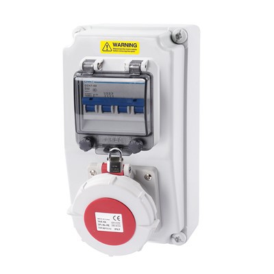

As a supplier of ABS Power Distribution Boxes, ensuring the integrity of the wiring within these boxes is crucial for both safety and optimal performance. In this blog, I'll share some effective ways to check the wiring integrity in an ABS Power Distribution Box.
Visual Inspection
The first step in checking the wiring integrity is a thorough visual inspection. This is a simple yet effective way to identify obvious issues.
Examine the Wiring Connections
Start by looking at the connections between the wires and the terminals in the power distribution box. Check for any signs of loose connections, which can be indicated by wires that are not firmly seated in the terminals or by visible gaps. Loose connections can cause arcing, which not only affects the performance of the electrical system but also poses a significant fire risk.
Inspect the terminals themselves for signs of corrosion or damage. Corrosion can impede the flow of electricity and lead to overheating. If you notice any corroded terminals, they should be cleaned or replaced as soon as possible.
Look for Physical Damage
Inspect the wires for any signs of physical damage, such as cuts, abrasions, or fraying. These can expose the conductive parts of the wire, increasing the risk of short circuits. Pay special attention to areas where the wires may be rubbing against sharp edges or other components in the box. If you find any damaged wires, they should be repaired or replaced to maintain the integrity of the electrical system.


Check the Wire Routing
Ensure that the wires are routed properly within the power distribution box. They should be neatly arranged and not overcrowded, as this can lead to overheating and make it difficult to identify and troubleshoot problems. Look for any wires that are crossing each other or are in contact with other components in a way that could cause damage.
Electrical Testing
After a visual inspection, electrical testing is necessary to confirm the integrity of the wiring.
Continuity Testing
Continuity testing is used to check if there is a complete path for the electrical current to flow through the wire. You can use a multimeter set to the continuity mode for this test. Connect one probe of the multimeter to one end of the wire and the other probe to the other end. If the multimeter beeps or shows a low resistance reading, it indicates that the wire has continuity, meaning there are no breaks in the wire. If there is no continuity, it means there is a break somewhere in the wire, and further investigation is needed to locate and repair the break.
Resistance Testing
Resistance testing measures the resistance of the wire. Each wire has a specific resistance value based on its length, cross - sectional area, and material. By measuring the resistance of a wire and comparing it to the expected value, you can determine if there are any issues with the wire. A significantly higher resistance than expected may indicate a damaged or corroded wire, while a lower resistance could suggest a short circuit.
Insulation Resistance Testing
Insulation resistance testing is used to check the integrity of the insulation around the wires. A high - resistance meter, also known as a megohmmeter, is used for this test. Connect the meter to the wire and the ground, and then apply a voltage to measure the insulation resistance. A low insulation resistance value indicates that the insulation may be damaged, which can lead to electrical leakage and safety hazards.
Thermal Imaging
Thermal imaging is a non - invasive method that can be used to detect potential wiring issues. A thermal imaging camera can detect hot spots in the wiring, which may indicate overheating due to loose connections, excessive current flow, or other problems.
Identifying Hot Spots
When using a thermal imaging camera to inspect the wiring in an ABS Power Distribution Box, look for areas that are significantly hotter than the surrounding areas. These hot spots can be early indicators of wiring problems. For example, a loose connection will often cause increased resistance, which in turn generates heat. By detecting these hot spots early, you can take corrective action before a more serious problem occurs.
Monitoring Temperature Changes
In addition to identifying hot spots, thermal imaging can also be used to monitor temperature changes over time. By regularly taking thermal images of the power distribution box, you can track any changes in the temperature of the wiring. A gradual increase in temperature may indicate a developing problem, such as a slowly corroding connection.
Documentation and Record - Keeping
Throughout the process of checking the wiring integrity, it's important to keep detailed documentation. This includes recording the results of the visual inspections, electrical tests, and thermal imaging.
Creating a Maintenance Log
Maintain a maintenance log for each ABS Power Distribution Box. In the log, record the date of the inspection, the type of tests performed, the results of the tests, and any actions taken. This documentation can be useful for future reference, especially when it comes to identifying trends or recurring problems.
Tracking Repairs and Replacements
Keep track of any repairs or replacements made to the wiring in the power distribution box. This information can help you determine the lifespan of the components and plan for future maintenance.
Conclusion
Checking the integrity of the wiring in an ABS Power Distribution Box is a multi - step process that requires a combination of visual inspection, electrical testing, and thermal imaging. By following these steps and keeping detailed documentation, you can ensure the safety and optimal performance of your electrical systems.
If you are in need of high - quality ABS Power Distribution Boxes or have any questions about wiring integrity, please feel free to reach out to us. We are here to provide you with the best products and solutions for your electrical needs.
References
- Electrical Installation Handbook, Schneider Electric
- National Electrical Code (NEC)