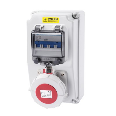

Hey there! As a supplier of High Current Distribution Boxes, I'm super stoked to chat about the electromagnetic shielding features of these bad boys. You see, in today's tech - savvy world, where electronic devices are everywhere, electromagnetic interference (EMI) is a real pain in the neck. That's where our High Current Distribution Box comes in, offering some top - notch shielding capabilities.
1. EMI Background in High-Current Power Distribution
In high-current distribution systems (typically 125A–630A and above), electromagnetic interference (EMI) is generated primarily by:
High di/dt switching of breakers and contactors
Harmonics from non-linear loads (LED drivers, VFDs, SMPS)
Long cable runs acting as antennas
Parallel routing of power and signal cables
Typical interference frequency range:
Low frequency: 50 Hz – 10 kHz (power frequency + harmonics)
High frequency: 150 kHz – 1 GHz (switching noise, RF coupling)
Without proper shielding, EMI can lead to:
PLC or control signal instability
Data transmission errors (Ethernet/RS485)
Nuisance tripping of protection devices
2. Shielding Materials and Structural Parameters
2.1 Enclosure Material Selection
Common materials and their shielding effectiveness (SE):
| Material | Thickness | Shielding Effectiveness (Typical) |
|---|---|---|
| Galvanized Steel | 1.5–2.0 mm | 60–90 dB (30 MHz–1 GHz) |
| Aluminum Alloy | 2.0–3.0 mm | 50–80 dB |
| Copper (localized shielding) | 0.5–1.0 mm | 80–100 dB |
Engineering Practice:
Main enclosure: powder-coated galvanized steel (≥1.5 mm)
Internal partitions or critical zones: copper or tinned copper shielding plates
2.2 Surface Treatment
Conductive coating or zinc plating ensures electrical continuity
Paint thickness controlled (typically 60–80 μm) to avoid insulating joints
3. Structural Shielding Design
3.1 Seam and Joint Control
Shielding performance is highly sensitive to mechanical gaps.
Design requirements:
Door-to-body contact resistance: < 0.1 Ω
Use of EMI conductive gaskets (nickel-graphite or silver-filled elastomer)
Gap width control: < 1 mm, ideally continuous contact
Typical shielding loss due to gaps:
A 1 mm स्लॉट at 300 MHz can reduce shielding effectiveness by 20–40 dB
3.2 Cable Entry Shielding
Cable entry points are the weakest part of shielding systems.
Recommended solutions:
EMC cable glands (360° shield termination)
Shielded cable clamps bonded to enclosure
Segregation of:
Power cables (high current)
Signal cables (low voltage, communication)
Example Configuration:
400A feeder cables via bottom gland plate
Shielded CAT6 / RS485 routed through separate EMC gland section
4. Grounding and Bonding System
Effective shielding depends on a low-impedance grounding system.
4.1 Grounding Parameters
Enclosure grounding resistance: < 0.1 Ω
Protective earth (PE) conductor sized per IEC (e.g., ≥50% of phase conductor)
Equipotential bonding between:
Door and enclosure (braided copper strap)
Mounting plate and enclosure
4.2 High-Frequency Grounding Consideration
At high frequencies, impedance is dominated by inductance:
Use wide, flat copper braids instead of round wires
Keep grounding paths short (<300 mm)
5. Internal Layout and EMC Zoning
Proper internal layout significantly improves EMI performance.
5.1 Functional Zoning
Typical segregation:
Zone A: High current switching (MCCB, busbars, 400A–630A)
Zone B: Power distribution (MCBs, contactors)
Zone C: Control & communication (PLC, meters, RS485/Ethernet)
Minimum separation distance:
Power vs signal: ≥100 mm or use metal partition
5.2 Busbar Design
Copper busbars with spacing per voltage level
Example (400V system):
Phase-to-phase clearance: ≥25 mm
Use of insulated or coated busbars reduces radiated emissions
6. Shielding Performance and Testing Standards
Shielding effectiveness is typically validated according to EMC standards.
Relevant standards include:
International Electrotechnical Commission IEC 61439 (assembly design)
International Electrotechnical Commission IEC 61000-6-4 (emission standard)
International Electrotechnical Commission IEC 61000-6-2 (immunity standard)
Typical test results for a well-designed enclosure:
Radiated emission reduction: ≥40–60 dB
Conducted emission compliance: within Class A industrial limits
ESD immunity: ±8 kV contact / ±15 kV air discharge
7. Practical Application Example
Scenario: Outdoor Event Power Distribution (400A System)
Configuration:
Input: 400A, 3-phase, 400V
Loads:
Stage lighting: 200 kW
Audio system: 80 kW
LED wall: 120 kW
Challenges:
High harmonic distortion from LED drivers
Long cable runs (30–80 meters)
Coexistence of power and DMX/control signals
Applied EMC Design:
Steel enclosure (2.0 mm) with conductive gasket
Separate cable zones for power and signal
Shielded DMX cables with 360° grounding
Internal partition between busbar and control section
Grounding resistance maintained at ≤0.05 Ω
Result:
Stable DMX signal (no flicker)
No false triggering of protection devices
Reliable operation over continuous 10–12 hour event cycles
8. Engineering Conclusion
Electromagnetic shielding in high current distribution boxes is a system-level design, not a single feature. Effective performance depends on the integration of:
Material conductivity and enclosure thickness
Mechanical sealing and gap control
Proper grounding and bonding
Cable shielding and routing strategy
Internal functional zoning
In high-load, high-interference environments such as industrial plants or event power systems, properly engineered shielding can improve system stability, reduce fault rates, and ensure compliance with EMC standards.

In conclusion, the electromagnetic shielding features of our High Current Distribution Box are designed to provide maximum protection for your electronic equipment. With high - quality materials, a well - thought - out design, and a reliable grounding system, our box is a top choice for anyone looking to combat electromagnetic interference. So, if you're in the market for a high - current distribution box, give us a shout, and let's start a conversation about how we can meet your requirements.
References:
- Electromagnetic Compatibility Engineering by Henry W. Ott
- Handbook of Electromagnetic Compatibility by Clayton R. Paul