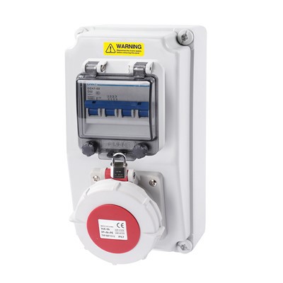

Standard Size of Industrial Distribution Boxes: Engineering Considerations and Practical Guidelines
In industrial electrical systems, the physical size of a distribution box (or distribution board) is not standardized in a universal sense. Instead, enclosure dimensions are determined by electrical load requirements, component configuration, installation environment, and compliance with applicable standards. Proper sizing is critical-not only for functionality, but also for thermal management, safety clearance, and future scalability.
1. Circuit Quantity and Load Density
The primary factor influencing enclosure size is the number of outgoing circuits and their respective load ratings. Each circuit typically requires protective devices such as miniature circuit breakers (MCBs), molded case circuit breakers (MCCBs), or fuses.
For example:
Small installations (4–12 circuits)
Typical enclosure size: approx. 400–500 mm (H) × 300–400 mm (W) × 150–200 mm (D)
Suitable for workshops, auxiliary systems, or localized equipment panels.
Medium installations (12–36 circuits)
Typical enclosure size: approx. 600–1000 mm (H) × 500–800 mm (W) × 200–300 mm (D)
Common in production lines, commercial facilities, or sub-distribution panels.
Large installations (36+ circuits / high current systems)
Floor-standing cabinets: 1800–2200 mm (H) × 600–1200 mm (W) × 400–800 mm (D)
Used in main distribution boards (MDBs), motor control centers (MCCs), and industrial plants.
These dimensions are based on typical DIN rail layouts, busbar spacing, and wiring requirements rather than arbitrary sizing.
2. Internal Component Configuration
The type and rating of internal components significantly affect enclosure size:
MCBs (DIN rail mounted) require relatively compact spacing.
MCCBs and ACBs (Air Circuit Breakers) demand larger mounting areas and clearance distances.
Busbar systems require spacing based on current rating (e.g., 250A, 400A, 800A, up to 6300A).
Auxiliary devices such as surge protection devices (SPD), energy meters, PLC modules, and communication gateways increase space requirements.
Engineering practice typically includes:
Minimum 25–30% spare mounting space for future expansion
Adequate wiring duct space (usually 20–30% of enclosure width)
Separation between power and control circuits for EMC compliance
3. Thermal Management and Ventilation
Heat dissipation is often underestimated but directly impacts enclosure sizing. High current devices generate heat, especially in densely packed panels.
Design considerations include:
Natural ventilation vs. forced cooling (fans, heat exchangers)
Internal temperature rise limits (typically ≤ 35°C above ambient per IEC guidelines)
Spacing between components to allow airflow
In high-load applications, engineers often increase enclosure depth or height to improve thermal performance rather than overcrowding components.
4. Environmental Conditions and Protection Rating
Installation environment determines both enclosure size and construction:
Indoor clean environments: compact wall-mounted enclosures (IP30–IP42)
Dusty or humid environments: larger sealed enclosures (IP54–IP65) with gasket systems
Outdoor installations: require additional space for rain shields, thermal insulation, and sometimes double-wall construction
Ingress Protection (IP) ratings per International Electrotechnical Commission standard IEC 60529 directly influence enclosure design and usable internal space.
5. Compliance with Industry Standards
Industrial distribution boxes must comply with internationally recognized standards, which indirectly define sizing and layout:
National Electrical Manufacturers Association (NEMA) enclosure types (e.g., NEMA 1, 3R, 4, 12)
International Electrotechnical Commission standards such as:
IEC 61439 (Low-voltage switchgear and controlgear assemblies)
IEC 60529 (IP ratings)
These standards define:
Minimum clearances and creepage distances
Mechanical strength requirements
Thermal limits and derating factors
6. Installation Method and Accessibility
Mounting type also influences size:
Wall-mounted enclosures: typically smaller, used for sub-distribution
Floor-standing cabinets: larger, modular, often used for main distribution
Modular systems: allow multiple panels to be combined for scalability
Accessibility requirements (front-only vs. front-and-rear access) will increase depth and overall footprint.
7. Future Expansion and Engineering Margin
From an engineering perspective, undersizing a distribution box is a common and costly mistake. Best practice includes:
Reserving 20–30% spare capacity for future circuits
Allowing additional space for retrofitting monitoring or automation systems
Designing with modular expansion in mind
This approach reduces long-term retrofit costs and avoids operational downtime.